
JA-110R
Service explanation for JA-110R
Radio Module
This product is a component of the JABLOTRON JA-100 alarm system. It enables wireless communication with wireless Jablotron 100 series components. Because of the expansion of the coverage area, up to three JA-110R modules can be used in the system. The product is intended to be installed by a trained technician with a valid Jablotron certificate.
Installation
The module can either be installed directly in the cover of the control center cabinet, or it can be placed in a suitable location in the house. Do not place the module near larger metal objects, also not near installations or pipes that may negatively affect wireless communication.
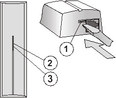
Figure:1 - snap clip of the screen; 2 - yellow signal light of interference; 3 - red signal light of communication
1. Open the screen (by pressing the snap clip 1).
2. If the module is installed in the cover of the central unit, screw the plastic back panel according to the figure.
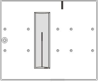
Figure: installation of the module in the cover of the central unit.
3. If installed on a wall in the house, prepare the supply of the BUS cable and mount the back panel in the chosen location (a vertical orientation is recommended).
Before connecting the BUS, the system must be disconnected from the power supply.
4. Connect the BUS cable to the terminals (the cable must not enter the antenna area when the screen is closed). If the module is installed in the cover of the central unit, connect the BUS via a cable through to the connectors.
The flat cable with RJ connectors should only be used for connecting the BUS up to max. length of 3 m.
5. Continue to follow the installation instructions for the central unit. Basic steps:
a. After power on, the yellow signal light (2) flashes because the module has not been read into the system.
b. In the F-Link program on the Peripheral Devices card, select the required position and start the learning mode with the Read button.
c. Press the tamper switch in the module (6) - which causes the module to learn and the yellow light will extinguish.
6. Close the cover of the module.
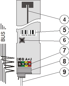
Figure: 4 - antenna; 5 - serial number; 6 - tamper switch; 7 - terminals of the BUS; 8 - connector of the BUS; 9 - cable with connectors (installation in the cover of the control center);
Set properties of the module
This is done by the F-Link program - card Peripheral devices. On the position of the module Use Internal setting. A dialog appears, where the following properties can be set:
LED indication at communication: from the factory it is set that at operation the module indicates communication with a wireless peripheral with the red signal light. You can disable this indication.
Failure detection: from the factory is off. However, it can be set to two levels - low (interference lasts longer than 30s over the course of a minute) and high (interference lasts longer than 10s for 20s). When the detection is on, the system is able to report the interference of the communication band.
Learning signal: by selecting this choice in the program use, the module sends a learning signal (intended for wireless peripherals, which contain only one receiver).
Technical parameters
Power supply from the BUS of the central unit 12 V (9...15 V)
Current consumption at standby (idle) 25 mA
Current consumption for cable selection 25 mA
Radiocommunication 868.1 MHz
Dimensions 150 x 40 x 23 mm
Classification grade 2
in accordance with CSN EN 50131-1, CSN EN 50131-3, CSN EN 50131-5-3
Environment in accordance with CSN EN 50131-1 II. indoors, general
Operating temperature range -10 to +40°C
Further complies with CSN ETSI EN 300220, CSN EN 50130-4,
CSN EN 55022, CSN EN 60950-1
Conditions of operation CTÚ VO-R/10/06.2009-9
Product has been designed and manufactured in accordance with the provisions to be applied thereto: Government Decree No. 426/2000 Sb. if used according to its intended use.
Note: Although this product does not contain harmful materials, do not dispose of it in the domestic waste, but dispose of it at the collection point designated for electronic waste.
Installation
The module can either be installed directly in the cover of the control center cabinet, or it can be placed in a suitable location in the house. Do not place the module near larger metal objects, also not near installations or pipes that may negatively affect wireless communication.
Figure:1 - snap clip of the screen; 2 - yellow signal light of interference; 3 - red signal light of communication
1. Open the screen (by pressing the snap clip 1).
2. If the module is installed in the cover of the central unit, screw the plastic back panel according to the figure.
Figure: installation of the module in the cover of the central unit.
3. If installed on a wall in the house, prepare the supply of the BUS cable and mount the back panel in the chosen location (a vertical orientation is recommended).
Before connecting the BUS, the system must be disconnected from the power supply.
4. Connect the BUS cable to the terminals (the cable must not enter the antenna area when the screen is closed). If the module is installed in the cover of the central unit, connect the BUS via a cable through to the connectors.
The flat cable with RJ connectors should only be used for connecting the BUS up to max. length of 3 m.
5. Continue to follow the installation instructions for the central unit. Basic steps:
a. After power on, the yellow signal light (2) flashes because the module has not been read into the system.
b. In the F-Link program on the Peripheral Devices card, select the required position and start the learning mode with the Read button.
c. Press the tamper switch in the module (6) - which causes the module to learn and the yellow light will extinguish.
6. Close the cover of the module.
Figure: 4 - antenna; 5 - serial number; 6 - tamper switch; 7 - terminals of the BUS; 8 - connector of the BUS; 9 - cable with connectors (installation in the cover of the control center);
Set properties of the module
This is done by the F-Link program - card Peripheral devices. On the position of the module Use Internal setting. A dialog appears, where the following properties can be set:
LED indication at communication: from the factory it is set that at operation the module indicates communication with a wireless peripheral with the red signal light. You can disable this indication.
Failure detection: from the factory is off. However, it can be set to two levels - low (interference lasts longer than 30s over the course of a minute) and high (interference lasts longer than 10s for 20s). When the detection is on, the system is able to report the interference of the communication band.
Learning signal: by selecting this choice in the program use, the module sends a learning signal (intended for wireless peripherals, which contain only one receiver).
Technical parameters
Power supply from the BUS of the central unit 12 V (9...15 V)
Current consumption at standby (idle) 25 mA
Current consumption for cable selection 25 mA
Radiocommunication 868.1 MHz
Dimensions 150 x 40 x 23 mm
Classification grade 2
in accordance with CSN EN 50131-1, CSN EN 50131-3, CSN EN 50131-5-3
Environment in accordance with CSN EN 50131-1 II. indoors, general
Operating temperature range -10 to +40°C
Further complies with CSN ETSI EN 300220, CSN EN 50130-4,
CSN EN 55022, CSN EN 60950-1
Conditions of operation CTÚ VO-R/10/06.2009-9
Product has been designed and manufactured in accordance with the provisions to be applied thereto: Government Decree No. 426/2000 Sb. if used according to its intended use.
Note: Although this product does not contain harmful materials, do not dispose of it in the domestic waste, but dispose of it at the collection point designated for electronic waste.